Having, the main parts identified, I had to arrange it somehow. I
thought of three different variants:
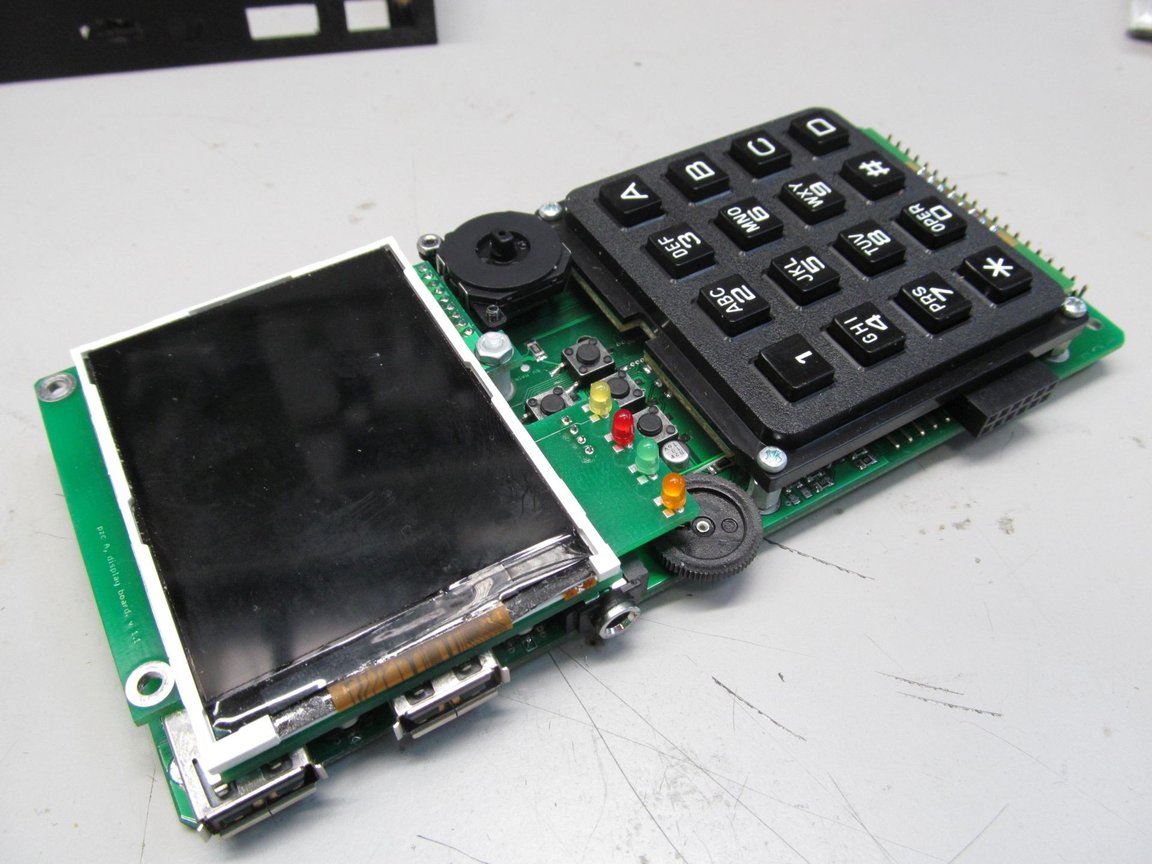
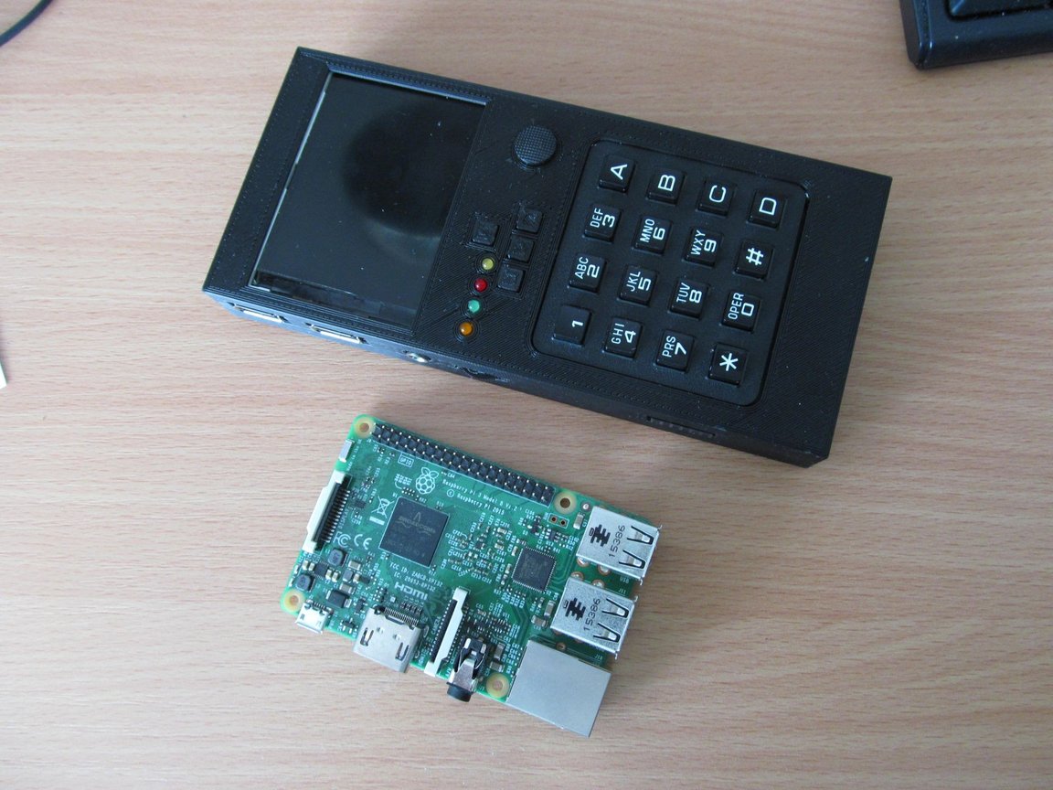
And third option (you can guess it's the winning one), display,
joystick and keyboard from top to bottom
I printed all three mock-ups on paper and tried to how it's going to
fit in my hand. Not surprising, the classic design, somehow resembling
old calculator or phone, is probably giving the best ergonomics from
all of those.
Brief summary of smaller details
Here I was at position to solve smaller details. Those details are
suited for separate log, though - so take this as a brief summary of
what I did.
I wanted to connect the keyboard in "simple" way, with no special
device drivers for raspberry pi, USB seemed like logical choice - so i
had to implement an USB HID device. The 12-key layout (actually 16-key,
but 4 of them used as modifier keys) makes it a bit harder, as normal
keyboards usually have one key per character, but it's nothing
unmanageable. I did the same for pavapro. Somehow more complicated was
to make "two-headed" HID device, allowing both keyboard and mouse
action via single USB device, realized in STM32F072C8 device.
For WiFi, I opted for RTL8188EUS module, available at usual Asian
sources. It is also common in many tablets or small computers on
market, it has even similar module in the same package (88W8782) so I
qualified it as jelly-bean part.
In order to have somehow useful computer, one USB port is not
enough, especially when consumed by on-board WiFi module and keyboard
interface. So I added USB hub with four downstream ports, with FE1.1s
chip. This one seems to be popular in "diy-handheld-console" guys too.
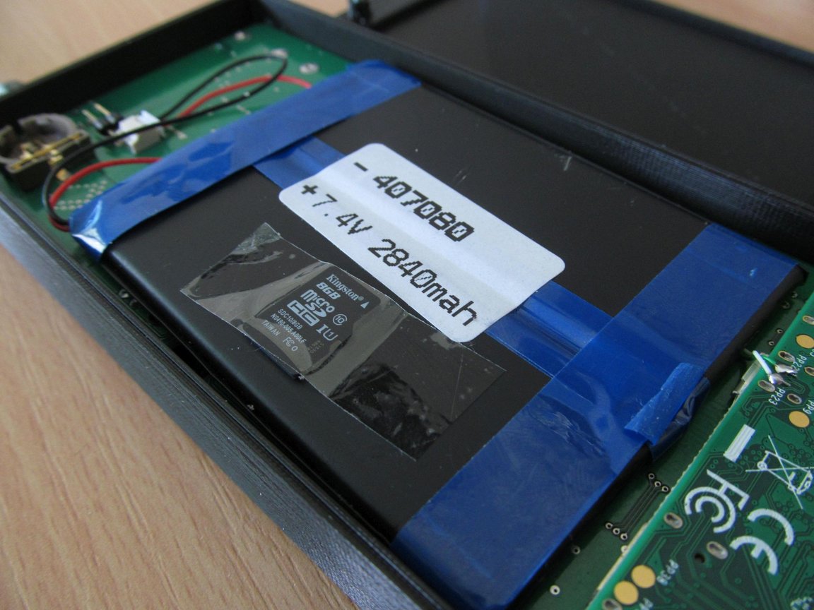
For all this, I need some kind of power. I opted for powering from
two Li-Po cells in series, with three step-down switched TPS562200
regulators - 5V for Raspberry pi, 5V for USB and 3,3V for WiFi module.
All those voltages are switched on or off via another MCU, STM32F030F4,
capable of communicating with Raspberry pi, so it can turn itself off,
if needed. The MCU can also monitor battery voltage and battery
charging.
PCB
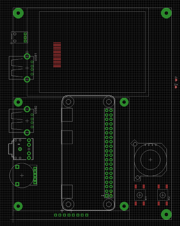
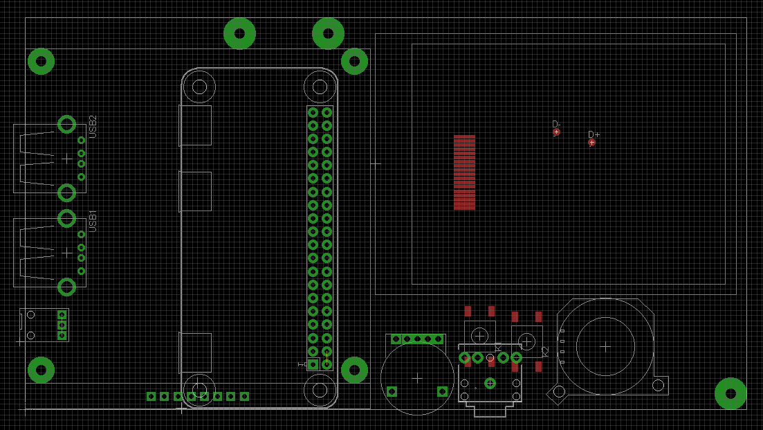
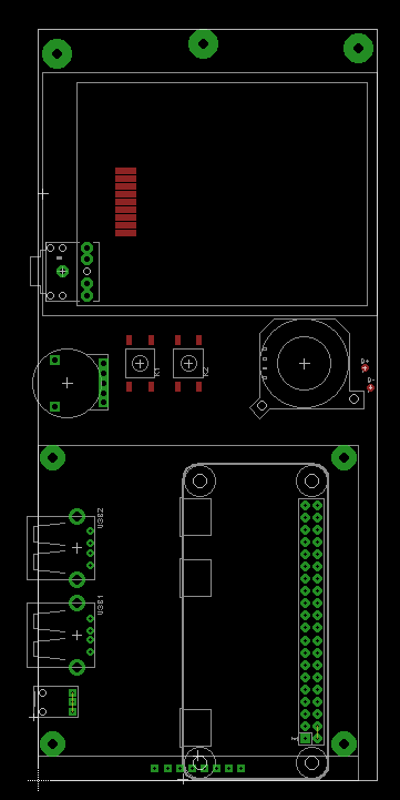
I took a few hours at Eagle and designed the PCB.
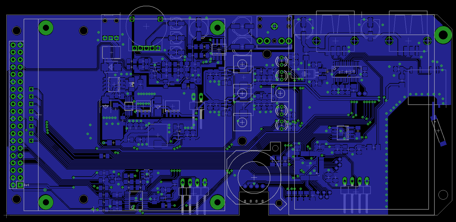
This is bottom side, top side being mostly groundplane. I ordered it
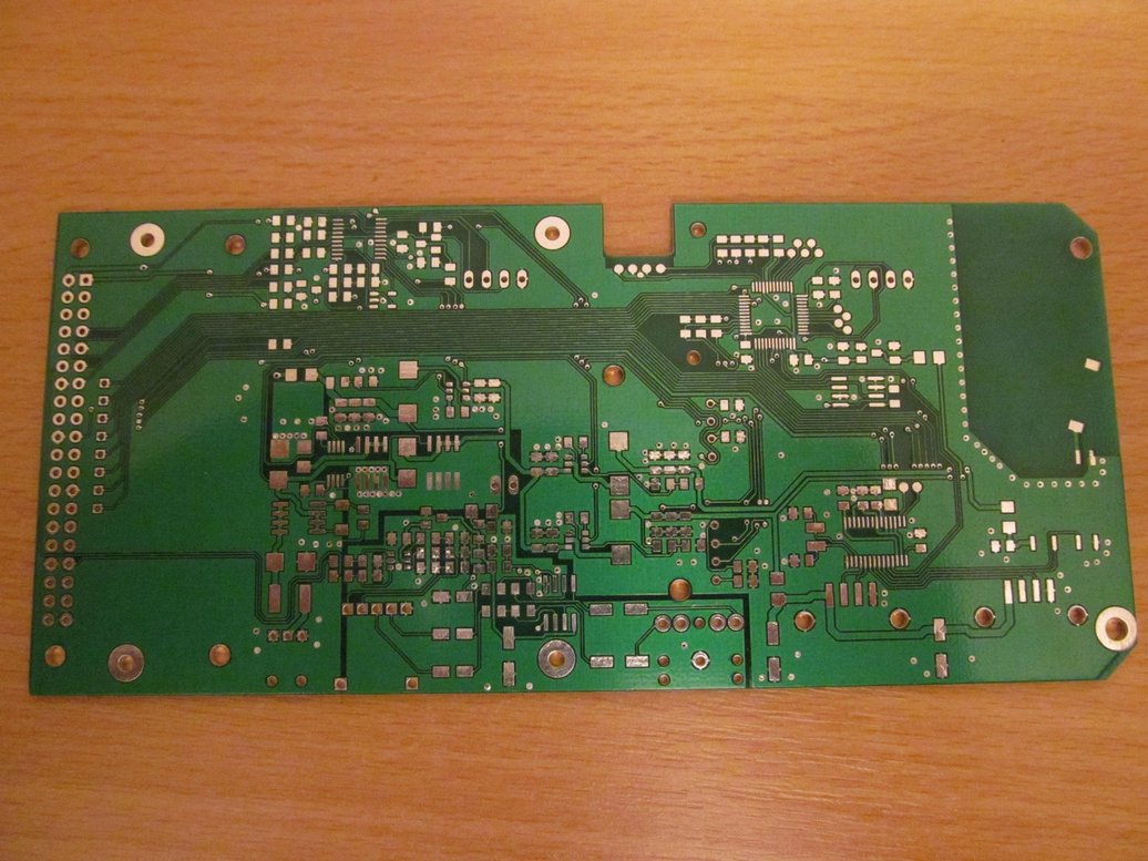
and...
..magic happened, PCBs were at my hands.
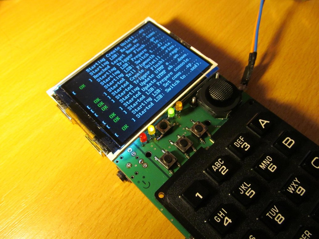
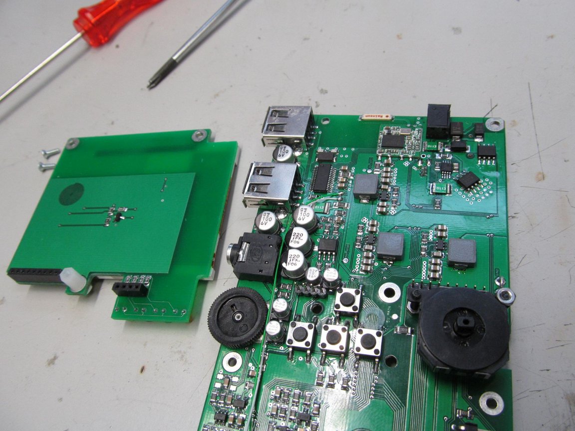
It didn't took me long to populate the board and correct some minor
mistakes
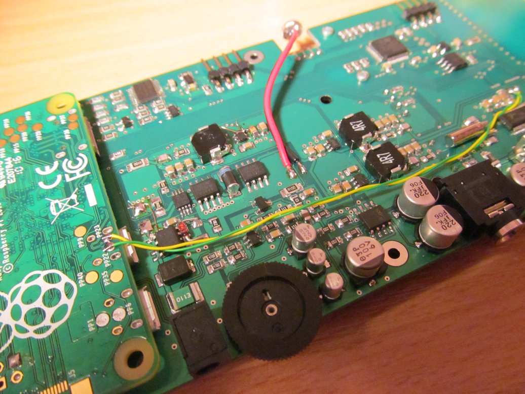
and to get it running
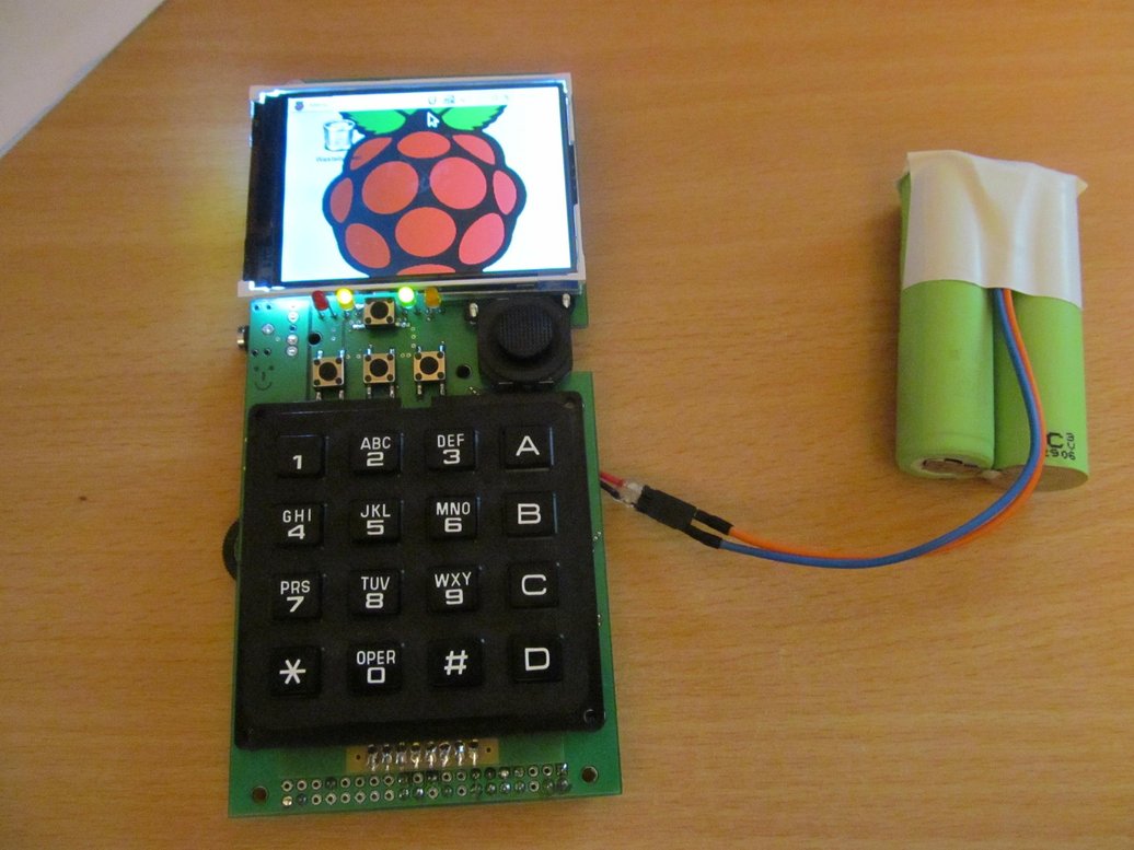
It took one more board revision and a little bit of coding to come
up with final hardware
In the meantime, I made some minor changes to circuit, but the
overall concept was still the same. Complete schematics is here https://github.com/jaromir-sukuba/pi_zero_computer/blob/master/hw/2i.sch.pdf
but for sake of simplicity here you have hand drawn block diagram
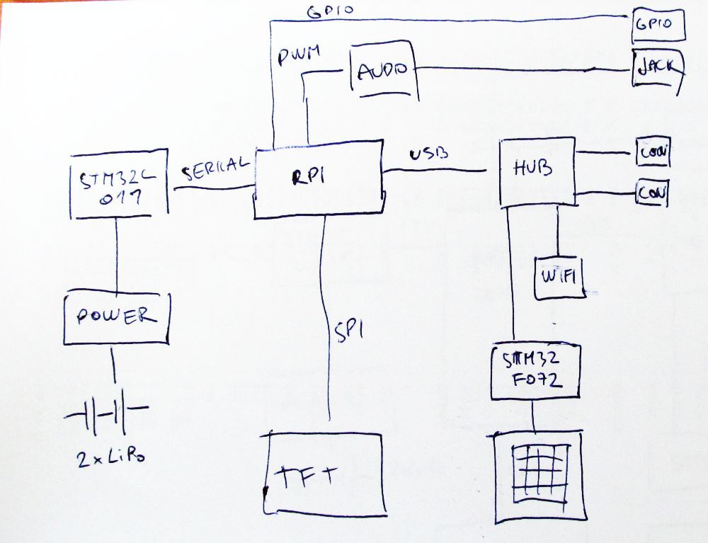
Heart of the device is Raspberry Pi Zero. The power is delivered
from two LiPo cells in series, MCP73844 acting as charging IC and three
TPS562200 are performing DC/DC down conversion to get three voltages:
* 5V for RPi
* 5V for USB
* 3,3V for WiFi
All of them are individually switchable from the STM32L011 and this
is under RPi control via serial interface (native serial port of RPi),
the STM can also report status of battery and charging controller. The
STM32L011 itself is always powered via MCP1700 voltage regulator. Power
consumption of the device in sleep mode is approximately 10uA.
Since RPi has only one USB port, I used FE1.1s USB hub IC to have
USB WiFi RTL8188EUS module and USB keyboard/mouse devices along
with two general purpose USB ports.

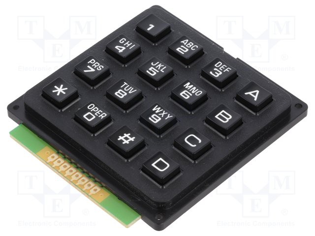
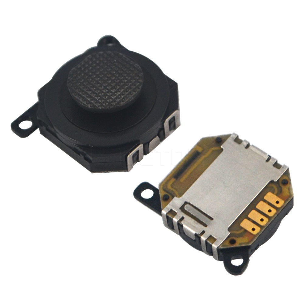
STM32F072 interacts with all tactile user IO (keyboard, joystick,
mouse buttons) and acts as USB HID device for RPi, with interfaces to
both keyboard and mouse. Since having 4x4 matrix keyboard (reasons why
I opted for this keyboard are here and here)
obviously brings some complications compared to full-blown 104 key
keyboard, so I had to be a bit creative about the key combinations
assignment. The bottom row keys act as modifier keys, but after a bit
of trying, it is not that hard to remember.
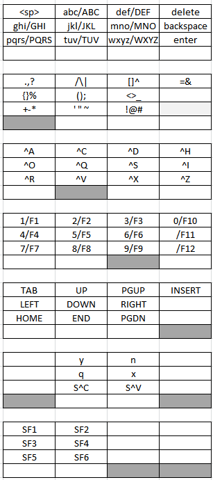
Gray keys denote pressed modifier keys. With no modifier keys
pressed, you have to top layout - press key 7 once, you get 'p', press
one more within 800ms, you get 'q', then 'r', then 's'. For special
characters, press first modifier keys. I tried to arrange them in some
logical manner, grouping related characters, like parenthesis or +-*
symbols. For running executables in bash, press left modifier, hit
first and second button, this types ./, then name of executable (using
tab key saves you some typing). Forethink the executable filenames at
least a bit and you can run most of them in a few key hits.
User interface is completed by TFT, with ILI9341 controller. It can be
bought through usual Asian sources. There is nothing special about it,
interfacing this kind of display has been done to death.
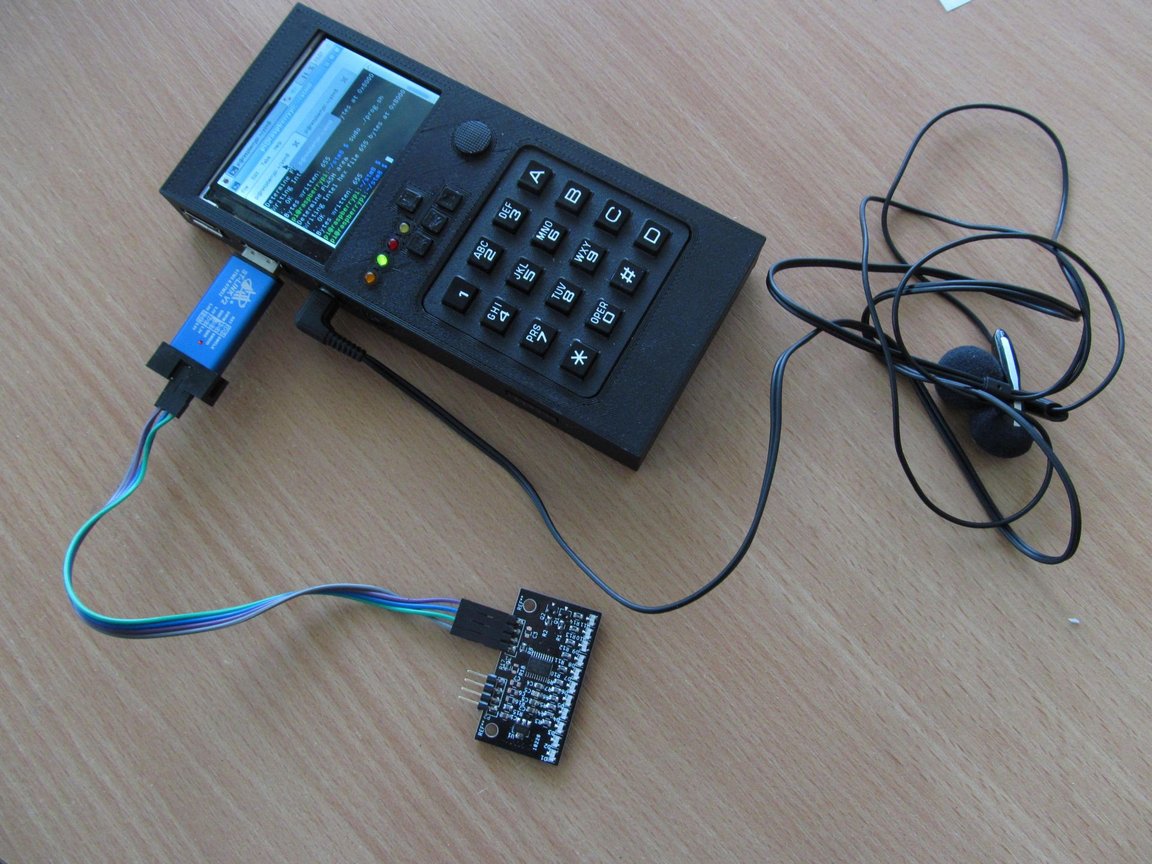
Audio is quite straightforward - the RC lowpass filter is no surprise
to RPi users, TDA1308 acting as headphone amplifier is jelly-bean
component, in intended application.
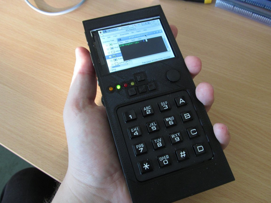
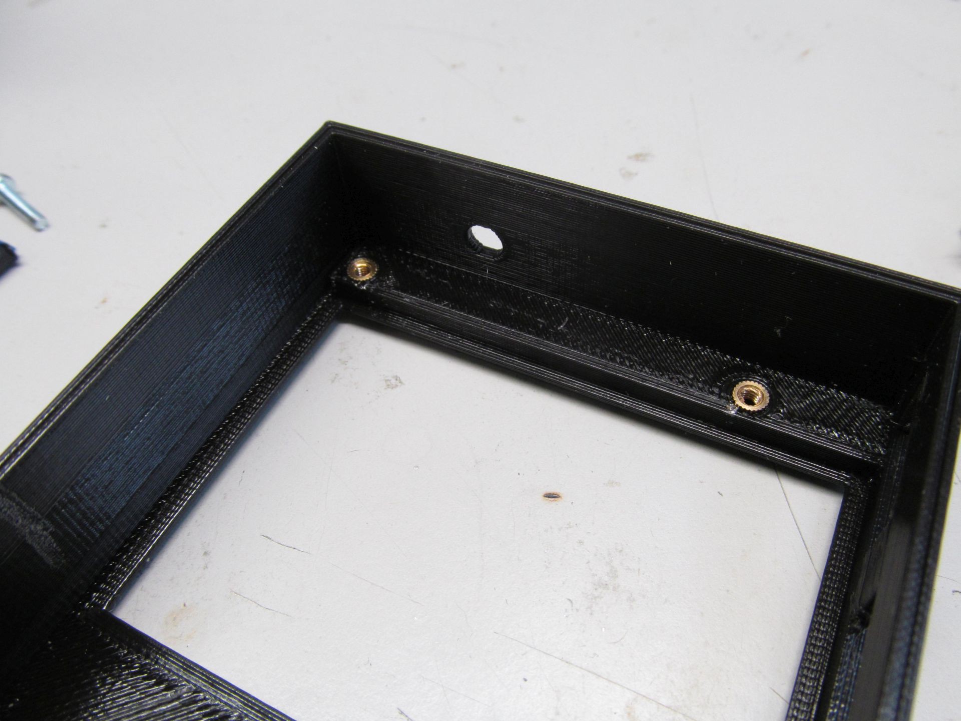
Enclosure is 3D printed, in three parts and is designed to keep the
whole package together using 4 pieces of M2,5 screws
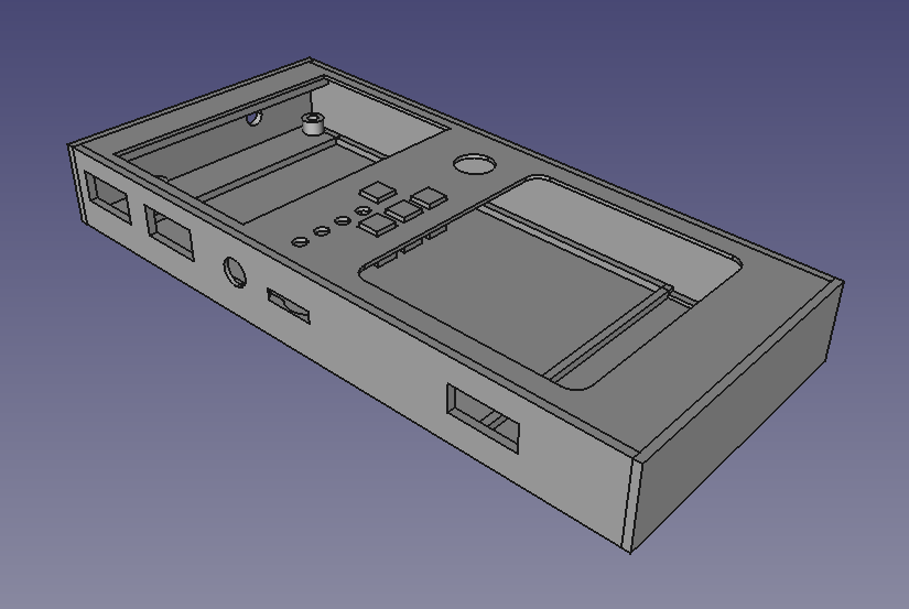
Threaded inserts are used to keep everything
in place and to allow repeated teardown of the case, so much needed
when tinkering with the device. Self tapered screws would be easier,
but not as reliable choice here.
Overall dimensions are 16,3x7,3x2cm
MODUS OPERANDI
As I wrote in FAQ - if you need to ask what is this project for, you
probably don't need it. I build it for my own enjoyment during design
and build, as well as machine to allow me to better learn
programming/scripting languages (and to listen to my favorite tunes
while doing so) and as ultimate nerd status symbol to carry around.
What about browsing web on lynx?
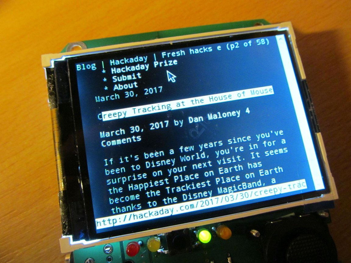
Chromium works here too, but due to small display it isn't very
enjoyable to use.
With SDCC
and stm8flash
I can edit, build and upload firmware on STM8 targets
or on arduino platform
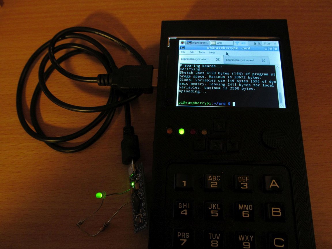
I'm pretty sure STM32 targets should work too, as well as PIC
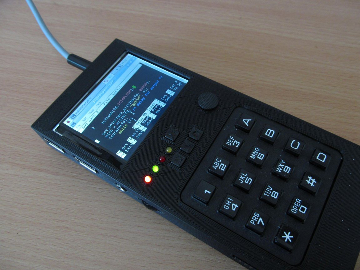
devices, using my programmer. Here you can see nano editor,
editing my code to talk with STM32L011 MCU onboard, reporting battery
voltage.
Oh and don't forget to backups. Here is my take on SD card backup
system.
Source files are to be found on
github